Overview of new international standards for the use of CFA (TFM)
CFA IS "RIPE"
There is a concept of technology maturity levels (technology readiness level — TRL), which describes the technology transition from the TRL 1 level. “The fundamental concept of technology has been formulated” to the TRL 9 level. “The product meets all requirements: engineering, production, operational, quality and reliability.” So the Total Focusing Method technology, aka digital antenna focusing (CFA), aka combinational SAFT, aka IWEX, aka Sampled Phased Arrays (SPA) has turned from an exotic and contested algorithm into a standardized one.
Although, to be fair, the first technique in Russia with the use of the CFA “The technique of ultrasonic inspection of composite welded joints for welding pipes of equalizing pipelines, welding pipes for injection of pressure compensators and welding SAOZ pipes of the VVER-440 reactor vessel to the adapter sleeve using phased array technology” was introduced back in 2012.
The AUGUR-ART flaw detector, which implemented this technique from the very beginning, was aimed at applying CFA and only then the FR technology was mastered.
At the beginning of 2021, two standards for the use of TFM in ultrasonic non-destructive testing were released:- ISO 23865:2021. Non—destructive Testing — Ultrasonic Testing - General use of the Full matrix Capture/Full Focus (FMC/TFM) method and related technologies
- ISO 23864:2021. Non—destructive testing of welds — Ultrasonic testing - Using the automated Full Focus Method (TFM) and related technologies
Below we will talk about some of the features of these standards and how the requirements of these standards are implemented in the AUGUR-ART flaw detector.
The following is intended for specialists who already know what an ultrasonic phased array is and what the digital antenna focusing method is.
Those who want to learn the basics of CFA/TFM are addressed, for example, to publications and presentations:
- Development of algorithms for ultrasonic flaw detection using antenna arrays [pdf]
- Comparison of the capabilities of ultrasonic non-destructive testing devices using antenna arrays and phased antenna arrays [pdf]
ISO 23865:2021 — Ultrasonic inspection / General principles of application of TFM and similar control methods
The standard is mainly used on isotropic materials, but recommendations are also given for use on anisotropic materials such as austenitic steel or with rolled anisotropy.
In any case, the control should be carried out according to a specially developed methodology.
The designation of control schemes has been brought to the standard level, which developers have in fact been using for a long time:
- L — L: radiation and reception of the longitudinal wave
- T — T: transverse wave emission and reception
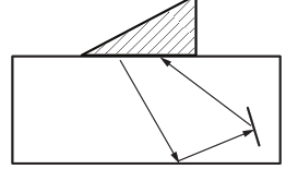
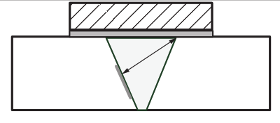
- TT — T: transverse radiation, transverse reflection from the bottom and transverse wave reception (in various publications in Russia it was called “odd SAFT”, “triangular scheme”, “back” pulses)
- TT — TT: radiation and reception of a transverse wave with reflection from the bottom
- , etc.
Directly in the standard it is stated that due to the principle of reciprocity (T — TT) and (TT — T) are the same, that is, the emitters with receivers can be easily swapped.

A comparison and comparison between TFM and the traditional use of phased arrays is carried out.
It is important that to collect the initial data, it is allowed to use not only a complete search of all combinations of emitter-receiver (classic FMC), but also a simplified version, such as PWI (radiation of a limited set of plane waves at different angles).
Interestingly, what is meant by that in the specification (what is it called in Russian - in the product documentation?) issues related not only to the evaluation criteria of the quality assessment, but also to the principles of measuring defects should be specified.
The personnel requirements indicate that in addition to the usual certification for the ultrasonic method (for example, according to ISO 9712), additional training is required using TFM flaw detectors on real or realistic defects.
Among the equipment requirements:
- The upper frequency band of the receiving path must be twice as high as the central frequency of the converter (this means that for the use of 10 MHz FR, the upper frequency band must be at least 20 MHz)
- The frequency of the ADC should be 5 times higher than the central frequency of the FR. And when using an algorithmic increase in the frequency of the ADC, the initial frequency should be at least 3 times higher than the upper limit of the FR bandwidth. Thus, for widely used 5 MHz antenna arrays, the frequency of the ADC should be set as 25 MHz in the first case and approximately 24 MHz in the second case. That is, the same value.
One of the fundamental points that is stipulated in the standard and this is very important: the principle of the choice of steps in the resulting image. A separate appendix C is dedicated to this.
It is clear that the larger the step, the faster the image acquisition is performed, but the higher the error of measuring the amplitude of the signal from the defect model or the real defect.
Once again, it is said that focusing for the antenna array, including in the CFA mode, is possible within the near zone determined by its active aperture.
The recommended pitch value for antenna arrays appears to be underestimated and is half the wavelength in the prism. There is no way to agree with this. In practice, there are no problems for a prism made of rexolite (the longitudinal wave velocity is 2.33 mm/mks) and a frequency of 5 MHz for a phased array with a pitch of 1 mm, and at the same time the wavelength in rexolite is only 0.46 mm.
The maximum allowable number of grid elements killed is one for every 16 and neighboring elements are not allowed to be killed.
From the scanning requirements — the recommended values of the scanning steps depending on the thickness are given. So for thicknesses up to 6 mm, a step of 0.5 mm is recommended, from 6 to 10 mm a step of 1 mm, for thicknesses from 10 to 150 mm a step of 2 mm. Here I would like to draw the attention of fans to set a step of 1 mm when checking welds with a thickness of 40 mm. Too much, comrades!
The methods of measuring are well known to those who have been dealing with holographic images for a long time, emphasizing diffraction signals at the tips of defects:
- taking into account the images formed
- by diffraction waves, measuring with a cutoff relative to the maximum of the display image
About control schemes taking into account the reflection from the bottom surface, it is briefly indicated that they should be chosen based on the proximity of the angles of incidence / reflection on the defect to the normal, also taking into account the transformation of the type of oxen. Use it effectively for operational verification.

ISO 23864:2021 — Ultrasonic inspection. Application of TFM for automated ultrasonic inspection of welds
The device of the standard itself is similar to ISO 13588. Non-destructive testing of welds — Ultrasonic testing — Use of automated phased array technology,
Similarly, it describes the levels of control (a concept that is difficult to find an analogue in domestic GOST). The control levels correspond to the probability of detecting defects by increasing the sounding schemes, so level A assumes control only on the direct beam, and level B — on the direct and reflected, level C — also with the addition of control schemes focused on the detection of planar defects along the boundaries of fusion.
Moreover, for level C, it is necessary to present sounding schemes in the control methodology. To do this, AUGUR is built into the software control scheme editor.
Curiously, there are no restrictions that arise when trying to visualize data obtained by applying a longitudinal wave with reflection from the bottom surface by simply extending the image recovery area. The fact is that such data require special interpretation, taking into account the waves transformed on the bottom surface from longitudinal to transverse.
The standard does not apply to anisotropic materials such as austenitic steel and to complex seams such as angular and incomplete penetration. At the same time, section 17 provides requirements for the control of austenitic steel seams.
With regard to the selection of the grid for obtaining images, it is recommended to use the method from ISO 23865. The requirements for phased arrays also repeat the recommendations of ISO 23865.
With regard to scanning devices, it is noted that the requirements for positioning relative to the weld are not as high as for other methods (meaning primarily zonal control).
However, the control procedure should reflect the limits of the deviation of the position of the sensors and it is necessary to show the effect of these deviations on the tuning samples.
It is stipulated that, depending on the design of the object of control, systems with scanning along the seam or along and across the seam are used. AUGUR systems include both single-coordinate and two-coordinate scanners for automated control.
The control zone for pipe welds with a thickness of more than 8 mm should include a 10 mm near-seam zone on the side. Which makes the task somewhat easier in comparison with 20 mm for seams with a thickness of more than 20 mm in Russian practice.
For measuring defects, both amplitude methods can be used (according to the data obtained by mirror reflection from a planar defect) so are methods based on the analysis of diffracted signals.
In the case of using the amplitude method, it is necessary to ensure the angle of incidence / reflection on the defect close to normal.
In general, for measuring vertically oriented defects, it is recommended to use a scheme with an odd number of reflections from the bottom (for example, T-TT).
Table 3 shows recommended image acquisition schemes depending on the type and location of the defect for seams with narrow and wide cutting.
- To analyze the data at the root of the seam, sagging of the root of the seam, it is recommended to use a separate data logging scheme with grids located on both sides of the seam. (an example of implementation in our article)
- To identify subsurface defects, it is allowed to use schemes with head waves, it is only necessary to justify that the chosen design of the prism allows you to excite head waves.
An interesting idea is proposed with control schemes by an antenna array mounted on a remote amplification roller, and with the use of several sounding schemes (called Top scanning in the text of the standard).
There are doubts about the effectiveness here — it is unclear how to make a damper/trap for signals that continue to run in delay.

A reservation is made that when controlling products of different thicknesses, complex welds of the welding type, the control level should be D, and the advantage of the CFA is the ability to take into account the changing geometry during online or post-processing.
As in other standards for the control of welds, it is stipulated that it is necessary to monitor the base metal, primarily for the presence of delaminations that can make it difficult to control the welds themselves.
When checking the settings, it is necessary that the signal-to-noise ratio for all areas of the image according to the control reflectors is at least 12 dB. The method of measuring the signal-to-noise ratio should be described in the control methodology. The AUGUR-Analysis software has a built-in module for calculating the signal-to-noise ratio.
An important addition in relation to the CFA is the permission to adjust the image area and sensitivity directly on the control object, but only for the A quality level.
It is allowed not to store the original A-scans, but images with the parameters of image acquisition.
Periodic verification of the settings can be carried out both on the original tuning sample and on some other sample with known characteristics. Which sounds pretty liberal.
A daily check of the functioning of the equipment as a whole is also required without specifying the criteria for functioning.
The verification requirements are quite simple: only for quality level D it is required to confirm the identification and measurement of reflectors in the tuning samples in the entire control area.
On assessing the quality of the collected data, it is indicated that the quality of the acoustic contact, the area of image restoration, sensitivity, signal-to-noise ratio, lack of saturation and data gaps should be checked.
All this requires special knowledge from the operator, acquired and tested during training.
Quality assessment. It is allowed to perform quality assessment according to amplitude or dimensional criteria.
When measuring by diffraction signals, it is allowed to determine the height by:
- diffraction signals from the top and bottom of the discontinuity
- one diffraction and one mirror signal from the discontinuity
- one diffraction signal and a known wall thickness
- one diffraction signal near the outer surface
If it is not possible to isolate diffraction signals, it is allowed to use various methods of measuring based on amplitudes (RF, ARD, conditional height at the level of 6 dB, etc.).
Among the requirements for the content of the conclusion based on the results of the control, the specifics of the use of CFA have been added:
- The dimensions and steps of the image restoration area
- are the results of checking the resolution, coverage and grid in accordance with Annex C of ISO 23865
Section 17 provides the procedure for applying this standard when conducting narrow austenitic welds:
- the highest level of control is applied – D, which requires the development of a control methodology, complex tuning samples
- are provided with the use of control methods of Appendix A from ISO 22825:2017
- settings, tuning samples must comply with ISO 22825:2017. It is allowed to use modeling for justification. Here we are faced with the legitimacy of the use of modeling for granular and anisotropic materials
- the general principles set out in ISO 22825:2017 are observed:
- If the properties of the material allow for a signal-to-noise ratio of at least 12 dB, it is allowed to apply the same rules as the control of pearlitic steel for materials with large grain, only longitudinal waves are used when passing through the deposited metal
- In the case of a signal-to-noise ratio of less than 6 dB, the possibility of applying other NC methods should be considered.
- The effect of anisotropy on the determination of the position and dimensions of the reflectors should be described
- it is recommended to use schemes with TTL wave type transformation
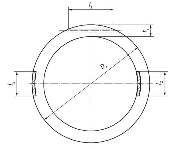
The designs of tuning samples are proposed depending on the level of control with the use of side holes, generally repeating the requirements of ISO 13588, an interesting innovation can be called the recommended design of the tuning sample for the control of pipes with a thickness of 2.5 to 8 mm.

The standard itself was prepared with the explicit participation of developers from Applus RTD (in any case, an application that includes characteristic images of typical weld defects obtained by CFA and compared with the results of metallography).
Conclusion
The CFA technology is standardized. Standards have been prepared that have the features of scientific research and leave room for creativity for developers of equipment and control techniques.
The AUGUR-ART flaw detector supports the main provisions of the new standards and is waiting for the crushing tasks of the field of ultrasound control.
Thanks for your attention!