Clustering of ultrasonic images of reflectors using an adaptive anisotropic diffuse filter
Introduction
The creation of automated recognition systems for reflectors based on images obtained by ultrasonic antenna arrays is a very urgent task. Its solution will increase the speed of preparation of inspection protocols and increase their reliability by reducing the influence of the human factor.
To effectively solve the problem of recognition (classification), it is necessary to prepare the image of reflectors in a special way. One of the stages is clustering (segmentation) of the image using a texture filter. Currently, there are many approaches to segmentation of optical images and the list below does not pretend to cover all types of texture filters.
- Adaptive anisotropic diffuse filter (in the foreign literature 2D or 3D AADF) [1].
- Modified method of fuzzy clustering of C-means (in foreign literature Modified Fast Fuzzy C-Means (FCM)) [2].
- Construction of the brightness dependence matrix (in the foreign literature Gray Level Co-Occurrence Matrix (GLCM)) [3].
- The method of fuzzy logic of the second type (in the foreign literature 2D Band-let Transform (2D BT)) [4].
- Algorithm for calculating the binarization threshold for a halftone image (Otsu's method) [5].
- Deep Claster technology (neural networks without training) [6].
It should be noted that in classical image processing, the method of histogram alignment is often used to improve contrast (in foreign literature Adaptive Mean Adjustment-Contrast Limited Adaptive Histogram Equalization (AMA-CLAHE) [7]). But here the question arises: "Will it be useful to "pull out" the amplitude of the glare of small reflectors in the presence of a inspection and rejection level for a specific inspection technique?". I believe that the development of technologies for recognizing discontinuities in welded joints will neutralize this methodological problem – the neural network will find reflectors and classify them without relying on the inspection and rejection levels.
The essence of the AADF clustering method is very elegant – the image is likened to the distribution of a diffusing substance in a medium with a certain diffusion coefficient at a constant temperature. Solving the diffusion equation by an explicit numerical method, one can observe the evolution of the original image with increasing time. But what is the diffusion coefficient for the processed image? In [1], a method for solving this problem was proposed by constructing a special function describing the diffusion coefficient depending on the gradient of the processed image. The greater the gradient of the image, that is, the steeper the edges of the image highlights, the lower the diffusion coefficient. And the smaller the gradient, the closer the diffusion coefficient is to unity. This approach leads to the fact that with an increase in the time of observation of the "diffusion" of the image, glare with sharp borders will dissolve poorly, and the steepness of these glare will practically not change. But insufficiently focused highlights will dissolve much faster and they will not be visible in the processed image.
Model experiments
To register echo signals in the double and triple scanning mode, an AUGUR ART flaw detector was used, developed and manufactured at the ECHOPLUS Research and Production Center [8].
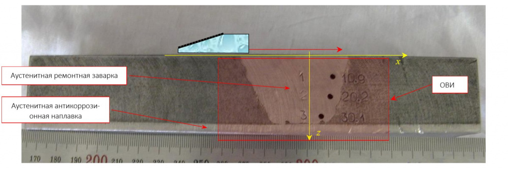
In a 38 mm thick sample with austenitic repair welding, three side drilling holes with a diameter of 2.2 mm were drilled (Fig. 1). The antenna array (32×(0.76+0.04), mm, 5 MHz) on a 20-degree prism moved along the sample surface 16 times in 1.0 mm increments (triple scanning mode). The red arrow corresponds to the size of the scan area.

Fig. 1. Photo of the inspection object
Figure 2 shows the reconstructed as a coherent sum of 16- and partial CFA images, CFA-X-image,. The image of the sample and the BCO is sketched on the image with lines of red color. The image clearly shows the glare of the sample bottom, the glare of the three BSOs, the structural noise of the repair welding and the glare of the interstitial non-melting.

Fig. 2. CFA-X-image
Figure 3 on the left shows the result of processing by 2D-AF of the CFA-X image shown in Figure 2, but after leveling its histogram. It can be seen that on the ADF image there are only the highlights of the day, the BTS and the intervalve non-melting. The structural noise of the repair welding has significantly decreased. Figure 3 on the right shows a vertical slice of a bitmap image along a dotted red line. Within the glare, diffusion led to a uniform dissolution of the "substance", which did not penetrate outside the glare due to the diffusion coefficient at the edge of the glare, tending to zero. It is important to note that the steepness of the glare has been preserved. The structural noise was uniformly "dissolved" and for this reason actually disappeared. When using simple smoothing filters, the glare of the BTS will blur, and the steepness of the edges of their borders will decrease.

Fig. 3. The 2D AADF image is shown on the left, and its vertical slice along the dotted red line is shown on the right
Since the measurements were carried out in triple scanning mode (there are 16 partial digital images – one for each position of the antenna array), there is a three-dimensional array of images to which the 3D-AADF method can be applied. Figure 4 shows the result of 3D-AADF processing of CFA images, which differs from what is shown in Figure 3 on the left by the greater compactness of glare.

Conclusions
- Adaptive anisotropic diffuse filter (AADF), developed for processing optical images, can also be used for processing images of reflectors recovered during ultrasonic testing. It can be used to increase the signal-to-noise ratio and to cluster the image of reflectors in order to prepare it for the recognition (classification) procedure.
- Contour detection programs work better on AADF images.
Eugene G. Bazulin
10-12 March 2021